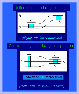
 In this diagram a fluid is flowing from left to right with a velocity of v. At the lower position (y1) the pressure P1 is higher than the pressure (P2) when the fliud is at the higher position y2.
Hydraulic and Pneumatic Systems Overall Expectations By the end of this course, students will:
Density Quiz with Answers Click Here
HYDRAULIC AND PNEUMATIC SYSTEMS INTRODUCTION
Learning Objective: Explain the operating principles of hydraulic and pneumatic systems. Identify the components, component functions, and maintenance procedures of hydraulic and pneumatic systems.
HYDRAULICS is a branch of science that deals with the study and use of liquids as related to the mechanical aspects of physics.
PNEUMATICS is a branch of science that deals with the study and use of air and other gases as related to the mechanical aspects of physics.
HYDRAULIC SYSTEMSThe extensive use of hydraulics to transmit power is due to the fact that a properly constructed hydraulic system possesses a number of favorable characteristics. These are as follows:
Pressure and Force
The terms force and pressure are used extensively in the study of fluid power. It is essential that we distinguish between these terms. Force means a total push or pull. It is push or pull exerted against the total area of a particular surface and is expressed in pounds or grams. Pressure means the amount of push or pull (force) applied to each unit area of the surface and is expressed in pounds per square inch (lb/ in 2 ) or grams per square centimeter (gm/ cm 2 ). Pressure may be exerted in one direction, in several directions, or in all directions.
Computing Force, Pressure, and Area
A formula is used in computing force, pressure, and area in hydraulic systems. In this formula, P refers to pressure, F indicates force, and A represents area.
Force equals pressure times area. Thus, the formula is written F = P x A
Pressure equals force divided by area. By rearranging the above formula, this state may be condensed into the following: P = F divided by A.
Since area equals force divided by pressure, the formula for area is written as follows: A = F divided by P
For all practical purposes, fluids are incom-pressible. Under extremely high pressures: the volume of a fluid can be decreased somewhat, though the decrease is so slight that it is considered to be negligible except by design engineers.
Liquids expand and contract because of temperature changes. When liquid in a closed container is subjected to high temperatures, it expands and this exerts pressure on the walls of the container; therefore, it is necessary that pressure-relief mechanisms and expansion chambers be incorporated into hydraulic systems. Without these precautionary measures, the expanding fluid could exert enough pressure to rupture the system.
Transmission of Forces through Liquids
When the end of a solid bar is struck, the main force of the blow is carried straight through the bar to the other end (fig. 3-2, view A). This happens because the bar is rigid. The direction of the blow almost entirely determines the direction of the transmitted force. The more rigid the bar, the less force is lost inside the bar or transmitted outward at right angles to the direction of the blow.
 In this diagram a fluid is flowing from left to right with a velocity of v. At the lower position (y1) the pressure P1 is higher than the pressure (P2) when the fliud is at the higher position y2.
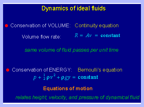 • Conservation of volume can be viewed in two ways:
The volume of a fluid passing by per unit time in the system is constant.
The produce of the area of the fluid times its velocity is also a constant which is the volume flow rate.
• Conservation of energy stipulates that at any point in a fluid flowing through some system the energy of the fluid is constant and is a sum of the fluid's pressure (P), kinetic energy (1/2 p v2), and gravitational potential energy (pgy).
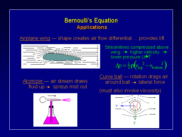 Three examples from everday occurences
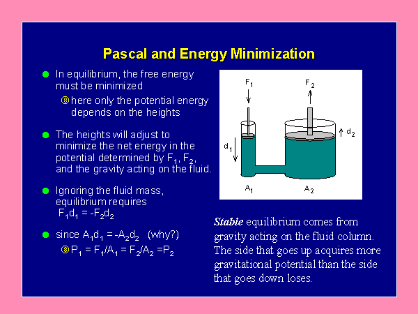
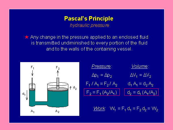 Pressure applied in cylinder #1 is transfered to
cylinder #2. However the work done on cylinder #1 is the same as the work done on cylinder #2. Forces may vary but the work done must be the same. This is based on the Law of Conservation of Energy; Energy cannot be created by a machine but forces may be changed as required. In this case a greater force will be produced in cylinder #2.
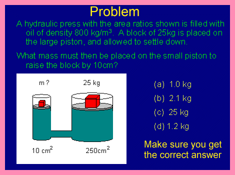 A simple multiple choice problem.
Use the above equation to sove and try Note#2 link and insert the correct values and let the program solve it for you. Be very careful with the units.
If you don't the answer make sure you get an explination.
 Pascal's Law An important property of fluid pressure is that if the fluid is at rest then the force it exerts at every outer surface must always be perpendicular to the surface. The surface it is in contact with exerts a reaction force which is equal and opposite and if this reaction force acting on the fluid had a component parallel to the surface then the fluid would be in motion in the direction of this component. The fluid therefore would not be at rest.
Pascal's Law states that any pressure P exerted on a confined fluid is transmitted throughout the fluid increasing the pressure at every point in the fluid by the same amount P. Since the atmospheric pressure acts on the free surface of the liquid, this is transmitted throughout the liquid increasing the pressure (hdg) at any point by the amount of the atmospheric pressure. As we already know this pressure (P+hdg) acts equally in all directions and the resultant force acting at the outer surface is normal to the surface. Two very useful devices based on Pascal's law are hydraulic brakes and hydraulic lift shown overleaf. The pressure applied by the foot on the break pedal is applied to the brake fluid contained in the master cylinder. This pressure is transmitted undiminished in all directions and acts through the brake pads on the wheel reducing the rotatory motion to a halt. Sliding friction between the tyres and the road surface opposes the tendency of forward motion reducing the linear momentum to zero.
 Hydraulic brakes
By means of hydraulic lifts, vehicles are lifted high on ramps for repairs and servicing. A force F applied on the cylinder of small area A, creates a pressure P=F/A which acts upwards on the ramp in the large cylinder of cross sectional area A'. The upward force acting on the ramp (being equal to F'= FA'/A) is much larger than the applied force F.
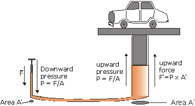 Hydraulic lift; the applied force may be many times smaller than the load force.
The pressure exerted by the person blowing into the straw is transmitted to the bag. But the bag has a much greater cross-sectional area than the straw, so the pressure forces exerted on the bag are huge.
Directions: To provide stability, a wooden square is placed on the bag. The person should sit squarely in the center. Have the students blow into the bag. (It doesn’t matter if there are small air leaks, or if the students stop to take a breath. The amount of air exiting the bag is small compared with the amount going in.)
Suggestions for Presentation: If you want to have fun with this one, ask if anyone would like to “blow up” the professor (or another student). Ask for volunteers to blow through the straws. (Incidentally, this would work with only one straw, but the time for it to happen would be insufferably long!)
Applications: Various hydraulic systems. Portable “air jack” systems.
 The ratio of load piston to effort piston determines the mechanical advantage of the system. In this diagram the mechanical advantage is 16.

To visit Note Two CLICK HERE
From the University of Oklahoma courtesy Dr. Michael Strauss, Associate Professor of Physics. 
Click on the OU. This is a pdf file and pages 3 to 10 are the relevant materials.