an HO scale slot car race track
![]()
![]()
![]()
![]()
![]()
![]()
![]()
![]()
![]()
Home Track Schedule Results and Points
 This will be the future Hillside Raceway Road Course.
The entrance and exit turns to the infield will not be nailed down so that they
can be moved to allow for straights to be put in to make an oval.
This will be the future Hillside Raceway Road Course.
The entrance and exit turns to the infield will not be nailed down so that they
can be moved to allow for straights to be put in to make an oval.

Back to Home Page
You can click on any of the pictures below to see them at full size (640x480).
This is a picture of the original Hillside Raceway Road Course. As you can see in the left foreground, the track had several crossovers to equalize the lane lengths somewhat. While it was fun with traction magnet cars, the T-Jets didn't like it. The other problem with the track was the track joints at the top of the two hills. One of the hilltops is at the beginning (far end) of the long straight and the other is at the short straight at the bottom of the picture. The hill in the long straight became a problem because T-Jets and magnet cars alike would catch some pretty good air and miss the set of crossovers on the down-side of the hill. The track joint was extremely peaked. The T-Jets would pick the joint and spin out, especially in the inside lane, and the magnet cars would hang up on the chassis at that joint. I also wasn't the happiest with this design, so I decided to start over and make a flat track so as to avoid "hill problems."

This is a picture over the top of the refreshment stand that will be relocated on the new layout. From this angle, you can see some of the hills.

This picture was taken after the track was removed from the table. It shows the 1/4" plywood sub-road that the track was nailed to. The brown square in the lower right hand corner of the picture is where the refreshment stand was.

This is another picture with the track removed. The old location of the refreshment stand is in the foreground. Once again you can see some of the hills from this angle.

This picture was taken after the sub-road was removed and broken down, and the cardboard scenery base was removed and destroyed. Those two parts will not be used in the future layout. This picture shows the 2"x4" risers that were used to create the hills in the original design. These too will be removed and scrapped.

This picture was taken after the risers were removed from the 1/2" plywood base, and the base taken off of the frame. Note that the left hand side of the frame is sagging. This was due to the cut-out for the power supply shelf. This will be fixed in the new layout.

This shot shows the old wiring for the track. Unfortunately (for those little wires), the wiring will be redone on the new track with some better grade materials.

This picture was taken after quite a bit of work was done. The old wiring was ripped out and discarded. Two new cross-braces were added to the original frame for added stability and to remove the sag in the drivers side (top side) of the frame. The new sawhorse legs are leaning up in front of the rebuilt frame.

This picture shows the new frame upright with the sawhorse legs underneath it. The table is a lot higher than it was when it was sitting on those milk crates :) Also, some holes were drilled in the framework to allow for the new wiring to pass through.

This picture shows the power supply/relay shelf. You can see three of the holes that were drilled for wiring paths.

This picture shows the new wiring in place. All of the power wires are 16 gauge stranded. The wires are connected to the drivers' stations by solder-less connectors (even though I did tin the wires before I crimped them into the connectors). In the shelf, you can see the power supply and the relay. Once I solder the proper wires from the relay cable onto the relay, the relay will be tacked in place on the far side of the shelf.

This picture shows the wiring for drivers' stations 3 and 4. The wires that are hanging straight down are the wires that will go to the track terminals.

This is a close-up of the power/relay shelf. The power supply is an old 18V 35W supply that I picked up off of Ebay. The unit is in great condition and supplies plenty of power for a four lane track.

I'm sure you can tell I've done a lot of work by the time I took this picture. The 4'x8' plywood top is on the frame, screwed down, and painted. The majority of the track is laid down, including a temporary back straight for the oval. As of right now, the temporary back straight is still in place because I just got the track to finish it off the right way today.

This picture shows the lane colors have been painted on to the majority of the oval and all of the road course infield section. This shot is of the main straight. It shows the small gaps in the track for the dead strip for the TrakMate timing program. To the right of the lower terminal section, you can see one of the catch-fence posts behind the "concrete" wall. The post is actually a nail with the head removed.

This picture shows a small portion of the infield. It also shows three of my T-jets and my Tyco Indy test car. When I say test car, that means wall/catch fence test car :)

This shot shows all of the infield of the track. In this shot, you can see that all of the "concrete" walls are in place, as are most of the catch-fence posts. The trees were placed temporarily to see how they would look.

This shot looks down the main straight. It shows how many catch-fence posts there are along the main straight. In all, there are 65 such posts on this track.
This shot shows the first section of catch fencing that was put up. The fencing is actually nylon screen that was cut down into a 2" strip. If you want an easy way to make your eyes go batty, cut a 2" strip of screen out of a 7' x 2' roll :)

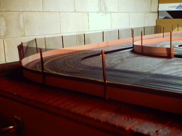
This shot also shows the first section of catch fencing. In the background, you can see that section of fencing ends right near the start/finish line. The fencing is attached to the posts with small pieces of copper wire wrapped around the post and through the fencing like small twist-ties. Eventually each of the copper ties will be super glued to the post to ensure that they do not move.

This picture shows the newly finished backstretch, complete with catch fence. The table has been completely cleaned off in preparation for the grass and trees.

Here is another angle of new backstretch with a great close up of the fence.

This isn't really a track construction shot, but what the heck. Nothing is all work and no play. Here I was playing around with the two Harris Specials that Earl sent me.

This picture shows the 98% finished product known as Hillside Raceway. As you can see, the trees are up, and the grass is growing :)

The refreshment stand in the infield offers food, soda, and shade from the nearby trees for the spectators.

Two drivers do some testing on the newly finished raceway. The Daytona leads the Chevelle into turn 1 of the road course. Eventually, there will be bleachers off of this and the other three corners of the oval/road course facility.
As mentioned above, the next portion of this project is to get some bleachers and some other scenic items. Right now the layout looks good, but it is a little bare yet. I don't know when I'll have the bleachers and/or other scenic items, but check back often to find out.
Back to Home Page
Created by Shawn Becher - sbecher@wi.rr.com - of Hillside Raceway on April 02, 2001